
Building Multiple Traffic Light Controller with a Cross Walk and an Emergency Buzzer
- Andy Huang
- Oct 24, 2019
- 6 min read

Updated: Oct 26, 2019
In the summer 2019, finishing up the class Introduction to Digital Devices CEIS114, we are working on a project to build a traffic light system with a motion sensor that give pedestrians time to pass the street with timer before green lights are turn on again. A set of emergency buttons are also implemented to hold the traffic by turning on a blue light to signal an incoming emergency.

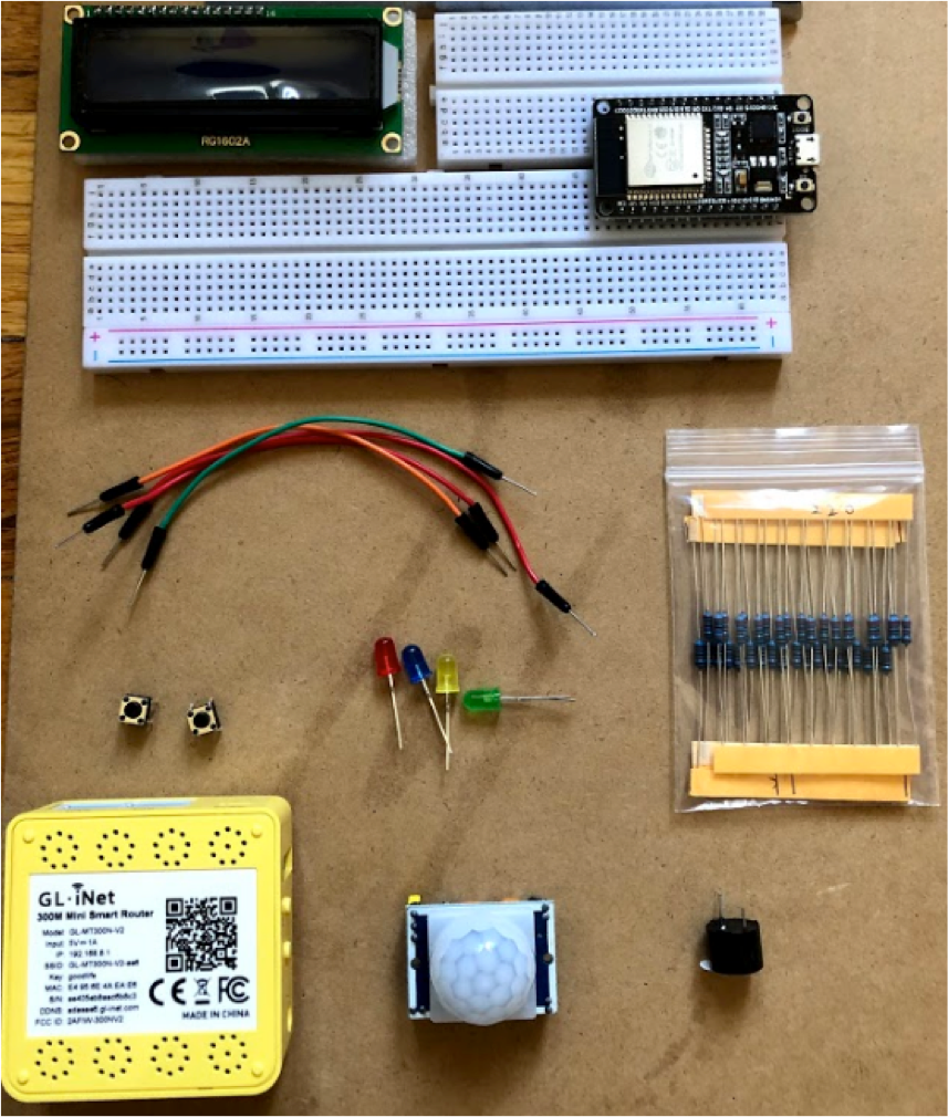
Gathering Materials
From the IoT Starter Kits, the items needed are:
ESP32 Board
Two sets of Colored LEDs: Red, Yellow and Green
One Blue LED
Push Buttons
LCD Unit
Buzzer
Motion Detector
Wires
Breadboard
Mini Smart Router (Optional) Unfortunately I find out this router isn't working till the end of the project
Testing first set of lights
First prototype is build to test the codes and the basic components for the circuit are working.
A little help with Flow Chart
After the basic circuit is working well, we use flow chart to show what will happen based on the conditions if there are pedestrian or motion detected to change the traffic light signals.

ESP32
This helps to identify which port to use

Two Sets of traffic lights
Next stage is to add another set of traffic lights and see they traverse from green to yellow then to red while the other set only has red light stays on. When one set of light ends on red light the other set will start cycling from green to yellow to red. The cycle keeps going as long as the power supply is available.

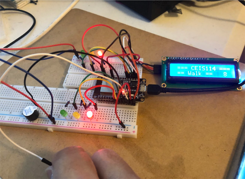
Adding LCD and Touch Sensor
With working sets of traffic lights we add the LCD and the touch sensor. Notice that I am holding the tip of a white wire that sends the signal to turn Red lights.
Final Result
Final prototype is finished with replacing the touch sensor(white wire in the previous photo) with the Motion Sensor and a Blue led light on top left of the breadboard. By pressing the button as shown in the video the Blue led will light up to indicate it's an emergency.
Codes and Serial Monitor Output
This is the code for the final stage and also the Serial Monitor that shows the outputs while the program is running
#include <Wire.h> //lcd
#include <LiquidCrystal_I2C.h> //lcd
LiquidCrystal_I2C lcd(0x27,16,2); //set the LCD address to 0x27 for a 16 chars and 2-line display
// if it does not work then try 0x3F, if both addresses do not work then run the scan code below
const int bzr=14; // GPIO14 to connect the Buzzer
// Set GPIOs for LED and PIR Motion Sensor
const int led = 16; // Flashing White (Blue) Led
const int motionSensor = 17;
int pirState = 0 ;
int j,Em_value,Xw_value;
const int Em_button = 23; // Emergency button
const int Xw_button = 19; //Cross Walk button
//==================== LCD ====================
// the setup function runs once when you press reset or power the board
const int red_LED1 = 4; // The red LED1 is wired to ESP32 board pin GPIO04
const int yellow_LED1 = 2; // The yellow LED1 is wired to ESP32 board pin GPIO02
const int green_LED1 = 15; // The green LED1 is wired to ESP32 board pin GPIO15
const int red_LED2 = 25; // The red LED2 is wired to Mega board pin GPIO25
const int yellow_LED2 = 26; // The yellow LED2 is wired to Mega board pin GPIO 26
const int green_LED2 = 27; // The green LED2 is wired to Mega board pin GPIO 27
void setup() {
//================Motion Detector initialization =====
// PIR Motion Sensor mode INPUT
pinMode(motionSensor, INPUT);
pinMode(Em_button, INPUT_PULLUP); // 0=pressed, 1 = unpressed button
pinMode(Xw_button, INPUT_PULLUP); // 0=pressed, 1 = unpressed button
pinMode(bzr,OUTPUT);
pinMode(led, OUTPUT);
digitalWrite(led, LOW); // Set Flashing White (Blue) Light to LOW
//=======================================
Serial.begin(115200);
lcd.init(); // initialize the lcd
lcd.backlight();
lcd.setCursor(0,0); // column#4 and Row #1
lcd.print(" === CEIS114 ===");// can be replaced with your name
pinMode(red_LED1, OUTPUT); // initialize digital pin 4 (Red LED1) as an output.
pinMode(yellow_LED1, OUTPUT); // initialize digital pin 2 (yellow LED1) as an output.
pinMode(green_LED1, OUTPUT); // initialize digital pin 15 (green LED1) as an output.
pinMode(red_LED2, OUTPUT); // initialize digital pin 25(Red LED2) as an output.
pinMode(yellow_LED2, OUTPUT); // initialize digital pin 26 (yellow LED2) as an output.
pinMode(green_LED2, OUTPUT); // initialize digital pin 27 (green LED2) as an output.
}
// the loop function runs over and over again forever
void loop() {
// Check the emergency button
int Em_value=digitalRead(Em_button);
if (Em_value == 0){ // Emergency button was pressed so allow about 10 seconds
skipnow: // jump here in case of emergency ====================
Serial.println("Emergency button was pressed ");
// Both sides are RED with flashing White (Blue) light
digitalWrite(yellow_LED1 , LOW); // This should turn off the YELLOW LED1
digitalWrite(green_LED1, LOW); // This should turn off the GREEN LED1
digitalWrite(red_LED1, HIGH); // This should turn on the RED LED1
digitalWrite(red_LED2, HIGH); // This should turn on the RED LED2
digitalWrite(yellow_LED2 , LOW); // This should turn off the YELLOW LED2
digitalWrite(green_LED2, LOW); // This should turn off the GREEN LED2
for (j=0;j<10;j++){ // total of 10 seconds, can be changed
digitalWrite(led,HIGH);
delay(500); //Flashing white (blue) light every .5 sec -- ON
digitalWrite(led,LOW);
delay(500); //Flashing white (blue) light every .5 sec -- OFF
}
} // End of (if) statement for Emergency button
Em_value=digitalRead(Em_button);
int Xw_value=digitalRead(Xw_button);
pirState = digitalRead(motionSensor);
if (Em_value == 1){ // Emergency button not pressed
if (pirState == 1 || Xw_value == 0 ){ // Emergency button not pressed, X-button or motion pressed
// Transition: If a button is pressed, yellow on major street for 1sec. before switching
if(pirState == 1){Serial.println("motion detected");}
delay(500);
digitalWrite(green_LED1, LOW); // This should turn off the GREEN LED1
digitalWrite(yellow_LED1, HIGH); // This should turn on the Yellow LED1
delay(1500);
digitalWrite(bzr, HIGH);
digitalWrite(yellow_LED1 , LOW); // This should turn off the YELLOW LED1
digitalWrite(green_LED1, LOW); // This should turn off the GREEN LED1
digitalWrite(red_LED1, HIGH); // This should turn on the RED LED1
digitalWrite(red_LED2, LOW); // This should turn on the RED LED2
digitalWrite(yellow_LED2 , LOW); // This should turn off the YELLOW LED2
digitalWrite(green_LED2, HIGH); // This should turn off the GREEN LED2
// LED1 is a major street
for (int i=10; i>= 0; i--) {
Em_value=digitalRead(Em_button);// check for emergency button pressing
if (Em_value == 0)goto skipnow; // if so break and execute emergency at skipnow label
Serial.print(" Count = ");
Serial.print(i);
Serial.println(" == Walk == ");
lcd.setCursor(0,1); // set the cursor to column 1, line 2
// lcd.clear(); // clears the display to print new message
lcd.print(" ");
lcd.setCursor(0,1); // set the cursor to column 1, line 2
lcd.print(" == Walk == "); // Print T= characters to the LCD.
lcd.print(i); // Print the temperature in F to the
delay(1000);
digitalWrite(bzr, LOW);
delay(500);
} // End of counter
// clears the display to print new message
// ===== lcd.clear();
lcd.setCursor(0,1); // set the cursor to column 1, line 2
lcd.print(" ");
//====================================
// Transition
digitalWrite(green_LED2 , LOW); // This should turn off the YELLOW LED2
digitalWrite(yellow_LED2 , HIGH); // This should turn off the YELLOW LED2
delay(1000);
} // End of Emergency button not pressed, X-button pressed or Motion was detected
} //End of Emergency button not pressed
//===============================================
// No motion, No Emergency, No crossing, then LED1=Green, LED2=Red always
lcd.setCursor(0,1); // set the cursor to column 1, line 2
lcd.print(" = Do Not Walk ="); // Print T= characters to the LCD.
Serial.println(" == Do Not Walk == ");
digitalWrite(yellow_LED1 , LOW); // This should turn off the YELLOW LED1
digitalWrite(green_LED1, HIGH); // This should turn off the GREEN LED1
digitalWrite(red_LED1, LOW); // This should turn on the RED LED1
digitalWrite(red_LED2, HIGH); // This should turn on the RED LED2
digitalWrite(yellow_LED2 , LOW); // This should turn off the YELLOW LED2
digitalWrite(green_LED2, LOW); // This should turn off the GREEN LED2
delay(1000);
//====================End Motion ==========
}// End of loop

Obstacles
During the entire project there are few obstacles required more attention
Obstacle #1: Ground port for black wire on the LCD
As shown on the circuit schematic, the LCD wasn't working because it's recommended to connect the black wire to the Ground blue on side of the breadboard. I have connected to the ESP32 ground port instead in order for it to work. It's towards the end of the breadboard and the 2nd port right above the red wire in the diagram.

Obstacle #2: LCD square fuse is missing
The LCD wasn't working during the first trial because there is a missing part. Notice these two exact same components but the fuse on the bottom LCD is missing so that one wasn't working so I order another 2 LCD as backup and found out the problem.

Acquired Skills
I am very satisfied with the end result and the guidance of the teachers. This is the first time I have programmed ESP32 with a LCD and the buttons. Unfortunately the mini wireless router wasn't working so I couldn't work on controlling the traffic lights with the cloud service but I will try to work on it after I order new parts.
Coding Python is getting more fun after this project because I can build a circuitry to direct the current to do what my program is designed to do.
Better troubleshooting is also another skill set I've acquired for both coding and on the hardware. I have to change the code so the LCD will work and also to check all the small details on the LCD and breadboard to make the project work. Not to forget to follow the diagram of the instructional manual to know which wire goes to which port.
This project has provided me with a great head start to acquire more skill on building different IoT devices in the future as I learn to program different sensors and actuators and other components. Thanks a million DeVry University professors!
Comentarios